Moving from DC to DCC: What Actually Changes in Your Wiring
DC to DCC isn't as complicated as it looks. Once you understand what actually changes, most of your existing wiring stays. Some of it goes away entirely.
Part 4: Moving from DC to DCC Wiring
Most DCC guides start by telling you what to buy and how to connect it. That approach only makes sense if you already understand the system, and most people reading a DCC wiring guide don’t.
The confusion isn’t the wiring itself. Understanding what actually changes, and what stays exactly the same, makes the rest straightforward. So that’s where this starts.
How DCC Works Differently
In DC, varying the track voltage controls the loco. Your controller sends 6V and the loco runs at half speed. It sends 12V and the loco runs faster. Every loco on that section of track responds to every voltage change. That’s why DC block wiring exists. You carve the layout into isolated sections so individual sections can be controlled separately.
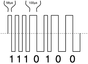
DCC removes that relationship entirely. The track voltage stays constant: around 16V on HO and OO gauge, 12V on N scale. What changes is the signal. The DCC command station sends a digital pulse train down the track, and each loco’s decoder listens for its own address only. A command addressed to loco 3 is ignored by locos 4, 7, and 22. They keep doing whatever they were last told.
This is what makes running multiple trains independently practical on the same track. It’s also the thing that changes your wiring approach from the ground up.
What Goes Away
Block wiring goes away. If you have an existing DC layout with isolated track sections, cab control switches, and separate power feeds for each block, most of that is no longer needed.
Each DC block required its own feed and switch because you had to cut voltage to sections where a loco was waiting. In DCC, the track is live everywhere, all the time. Locos stop because they receive a stop command, not because their power is cut.
On a straightforward layout, removing DC block control is simple: bridge any track gaps installed purely for block isolation, remove the cab control switches, and run a proper DCC bus. The one exception is reversing loops. Those still need gapped rails and either a manual polarity switch or an auto-reverser module, because the physics of the short circuit they create hasn’t changed.
What Stays the Same, and Gets More Important
The bus wire stays. In fact, the DCC bus needs to be better than a typical DC bus.
DC runs at 12V with modest current demands. DCC runs at 16V and must supply clean, consistent power to every decoder on the layout simultaneously, including sound decoders that draw significantly more current than standard motor-only units. The DCC signal needs to arrive at every point on the layout without degradation. A marginal bus connection in DC might cause a loco to slow slightly. The same connection in DCC causes decoder errors, address misses, or random stops that are difficult to trace.
Use 14 AWG stranded copper for DCC bus runs over 3 metres. For shorter layouts, 16 AWG is acceptable. The same principles from Part 1 apply: one run for each rail, colour-coded, feeders every one to one-and-a-half metres, solder every feeder joint. The installation process from Part 3 applies here without modification. The bus and feeders work identically.
Use 16 AWG stranded tinned copper in the UK, 14 AWG stranded hook-up wire in the US, or 16 AWG silicone stranded wire in Australia.
Power Districts: When You Need Them and How They Work
On a small layout, an oval or simple point-to-point up to about 2x1 metres, one DCC bus and one command station is all you need.
Larger layouts need power districts. A power district is a section of track separated from the main bus by a circuit breaker. When a short occurs in that district, the breaker trips for that section only. Common causes: a derailment, a loco bridging a gap. The rest of the layout keeps running.
Without districts, any short trips the entire command station. The whole layout goes dark. With districts, a derailment on the back sidings kills only that section. The main running lines stay active.
Each district needs its own circuit breaker installed between the main DCC bus and that section’s feed. The DCC Specialties PSX1 adds auto-reversing capability alongside short-circuit protection, which is useful if one of your districts contains a reversing loop. At $45-50 it handles both jobs. The NCE EB1 covers short-circuit protection only at around $25-30 in the US and £22-25 from DCC Concepts in the UK [ASIN-NEEDED: NCE EB1 on Amazon]. Both work with any DCC command station.
For a first DCC layout, don’t plan power districts until the layout exceeds roughly 3x2 metres or you’re regularly running more than six locos simultaneously. Below that threshold, the added complexity isn’t worth it.
Decoders: Three Situations You’ll Encounter
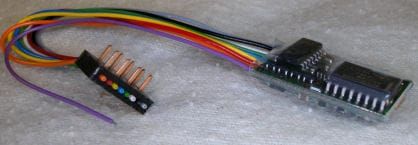
The decoder is the small circuit board installed in each locomotive. It receives DCC commands addressed to its programmed number and controls the motor, lights, and any additional functions accordingly. There are three situations you’ll run into.
DCC-Ready means the loco has a socket installed but no decoder. A blanking plug sits in the socket to keep the loco running on DC. Remove the plug, insert the correct decoder for that socket type, and the loco works on DCC. Most Hornby, Bachmann, and Dapol models made since around 2010 are DCC-ready. It’s the most common situation for modellers upgrading an existing fleet. Most of the locos I’ve converted have been DCC-ready — pull the blanking plug, insert the decoder, and it’s done in under five minutes.
DCC-Fitted means the decoder is already installed at the factory. Buy the loco, put it on the layout, assign an address using your command station. Nothing else to do. Hornby locos in their Digital and Railroad Digital ranges ship this way.
Hardwire is for older locomotives with no socket at all. A decoder with flying leads gets soldered directly to the motor terminals. Straightforward for experienced modellers but not the right first project. If you have a collection of pre-2005 locos, start with the DCC-ready ones and come back to the hardwire installations later.
Socket Types
For OO gauge in the UK, the three common socket types are: 6-pin NEM651 (most Hornby locos), 8-pin NEM652 (many Bachmann and Dapol models), and 21-pin (newer Bachmann models and some Dapol). Check which socket your loco has before ordering a decoder. The spec sheet or the manufacturer’s product page will confirm it. Inserting the wrong connector won’t work and risks damage.
The Bachmann 36-568A is a reliable 6-pin decoder for OO at around £15-18 from Rails of Sheffield or Hattons. It includes Back-EMF for smoother slow-speed running and RailCom support. For 8-pin and 21-pin installations, DCC Concepts Alpha decoders sit at the well-regarded end of the budget range.
For US HO modellers, the NMRA standard 8-pin plug (NEM652) is the most common socket in modern HO locomotives. TCS and Digitrax both produce reliable 8-pin decoders in the $18-28 range [ASIN-NEEDED: TCS M1 or Digitrax DH126D]. If you want sound, Soundtraxx Tsunami2 and ESU LokSound cover the serious end of that market.
Which DCC System to Buy
UK
The NCE PowerCab is the standard recommendation and has been for well over a decade. Two amps handles most home layouts, enough for six to eight standard HO/OO decoders simultaneously, fewer if running multiple sound decoders at once. It has a proper programming track output, which matters: DCC programming sends a short burst of higher current and some budget systems handle this badly, causing decoder errors. The PowerCab handles it correctly.
Around £189-195 from Coastal DCC or Rails of Sheffield. The PowerCab can be expanded to a full multi-cab system if your layout grows.
The Hornby R8213 Select at around £120 with power supply is the simpler entry point. It suits smaller layouts and is straightforward to use, but it doesn’t expand beyond a handful of locos and lacks the programming track output finesse of the NCE. Good for a single-board layout with a modest fleet; limiting for anything larger.
US
The Digitrax Zephyr Express at $230-250 provides 3 amps, a built-in command station and throttle, and a colour LCD display. Three amps gives more headroom than the 2-amp NCE for larger fleets, particularly ones with multiple sound decoders. It connects to the Digitrax LocoNet system if you want to add cabs or throttles later.
The NCE PowerCab at $175-200 is the more expandable option and the one that dominates club layouts where multiple operators share the system. Both handle most home layouts without issue. The Digitrax offers more current out of the box; the NCE offers a cleaner upgrade path.
Australia
The NCE PowerCab ships via Amazon AU at around AUD$280-320. Local hobby shops including Hobbyco in Sydney and Eureka Models carry DCC systems with in-store support, worth the price premium for a first DCC purchase. The Digitrax Zephyr is also available through eBay AU from US sellers, typically AUD$340-380 all-in with freight.
Upgrading a Working DC Layout
I’ve converted two layouts from DC to DCC. The actual rewiring took a couple of hours each time. Most of that was checking work I’d already done correctly. If you work in sequence it goes quickly.
First, assess the bus. If the DC layout already has a bus in place, check the wire gauge. Upgrade to 14-16 AWG if the existing bus is lighter. Check all feeder connections and reflow any that feel marginal.
Second, bridge any track gaps that were installed purely for DC block control. Leave gaps at reversing loops in place.
Third, remove the cab control switches. The bus now connects directly to the DCC command station. Those switches are no longer in the circuit.
Fourth, connect the command station and program your first loco. The NMRA default address is 3. Change it to something meaningful for your fleet. Most command stations walk you through this with clear on-screen prompts.
Fifth, run a test session with one loco before converting the rest. Confirm the DCC signal is clean and consistent across the whole layout. The AstroAI multimeter on AC voltage mode should read 16-18V consistently at any two points on the track with the system running.
The DC controller can go on a shelf. Some modellers keep it for programming track use. A separate low-current DC supply on a short section of isolated track lets you program decoders without putting the full DCC signal across the entire layout. Worth keeping rather than selling.
Parts 1 through 3 cover the DC foundation this part builds on: bus wire, tools, and wiring a working DC layout.