What is DCC? A high level overview to Digital Command Control for Model Railways
C stops making sense the moment you want two trains running independently. Here's how DCC actually works — from the signal in the track to programming CVs, fitting decoders, and choosing a command station from entry-level to the ESU ECoS.

You've got a starter set. You've run it round the oval a dozen times. The locomotive looks good, it runs smoothly, and you're starting to think about what comes next. Then you see two trains running independently on a layout, each under separate control, one creeping into the station while the other thunders through on the main line.
On DC, that isn't happening without a lot of electrical gymnastics. On DCC, it's exactly how the system is supposed to work.
This article is an introduction to Digital Command Control — a broad overview of what it is, how it works, and the main components you'll encounter. Each section here (decoders, CVs, sound, command stations) is a subject in its own right, and we'll be going deeper on all of them in separate articles. But if you're trying to understand what DCC is and whether it makes sense for you, this is the right place to start.
The Problem with DC
Traditional analogue DC control is simple and it works: you put voltage on the track, the locomotive moves. Increase the voltage, it goes faster. Reverse the polarity, it goes the other way.
The fundamental limitation is that the track is the controller. Every locomotive on the same section of track responds to the same voltage. There's no way to address them individually, which creates a cascade of problems the moment you want to do anything more than run a single train round a loop.
Lighting. On DC, the lights are powered by the track voltage. At low speeds, the voltage is low, so the lights are dim or flickering. At a standstill, many locomotives have no lights at all. It looks nothing like the prototype, where cab lights and headlights are on regardless of speed.
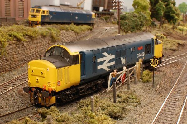
Multiple locomotives on the same track. If two locos are on the same section of track, they receive the same voltage and move at the same speed — or try to. Because every locomotive has slightly different motor characteristics, they'll run at different actual speeds even at the same voltage setting. Trying to run a Hornby Class 37 and a Bachmann 08 shunter at the same throttle setting will result in one locomotive bashing into the other. Speed-matching locomotives on DC is a genuine problem with no clean solution.
Block control. The workaround for running multiple trains is to divide the layout into electrically isolated sections, each fed by its own controller. A locomotive sitting in a siding can be isolated from the main line; a second controller handles the station approach while the first handles the main run. This is called cab control or block control, and it works — but it requires planning the layout's wiring from the outset, installing insulated rail joiners at every block boundary, and managing a panel of switches to assign blocks to controllers. On a simple oval it's manageable. On a layout with sidings, a terminus, a goods yard and a loop, you're dealing with dozens of isolated sections and a switching matrix. I've seen layouts where the wiring underneath takes longer than the scenery on top.
Reversing loops and triangles. On DC, a reversing loop has a polarity problem: as the locomotive enters and exits the loop, the rail polarity reverses, causing a short circuit. Solving this requires isolating the loop and manually switching its polarity as locos enter and exit. Automated reversing loop modules exist, but it's another layer of complexity.
Short addresses are the whole address. On DC, there's no concept of addressing at all. The throttle controls everything on the same circuit simultaneously. There's no way to give one locomotive a momentum simulation while another runs without it. Every setting that affects running behaviour — if the controller supports such things at all — applies universally.
DCC solves all of this at the root, not by working around the limitations of DC but by rethinking how control information gets to the locomotive in the first place.
How DCC Actually Works
To understand DCC, it helps to think about what's actually happening in the rails.
On DC, the track carries a simple electrical current, and the strength of that current (the voltage — think of it as the "pressure" behind the electricity) is what controls the locomotive. Turn the controller up, the voltage rises, the motor spins faster. Turn it down, the motor slows. The track is doing two jobs at once: delivering power to run the locomotive, and carrying the control signal (which is just the same current varying in strength).
DCC separates those two jobs entirely.
Under DCC, the track carries a constant, full-strength electrical signal at all times. The voltage doesn't go up and down with a throttle — it's always on, always at full power (typically around 14–16V for OO and HO gauge). What changes is the information layered on top of that signal.
The command station sends a rapid stream of digital instructions down the track — think of it like a radio station broadcasting continuously. These instructions are called packets, and each packet is addressed to a specific locomotive. If you're familiar with how text messages work, the idea is similar: every message has a recipient, and only the right recipient acts on it. A packet addressed to loco number 17 says, in effect: "loco 17, run at speed step 12, direction forward, function 2 on." The command station sends hundreds of these packets every second, cycling through all the active addresses on the layout.
Inside each locomotive is a decoder — a small circuit board, often no bigger than a stamp. The decoder does three things: it picks up the digital signal from the track, reads the packets addressed to its own number, and translates those instructions into actual motor and lighting control. A packet telling loco 17 to run at speed step 12 causes the decoder to send the right amount of power to the motor to achieve that speed. Packets for loco 23 or loco 8 are simply ignored.
Speed steps are worth understanding briefly. Rather than a smooth analogue dial, DCC throttles work in steps — most modern systems use 28 or 128 speed steps between stopped and full speed. 128-step mode gives much finer, smoother control than 28-step, and most decoders support it. You'll see this referred to in decoder specifications and command station settings. For most modellers, 128-step mode is the default and you won't need to think about it much beyond that.
The practical result of all this is that every locomotive on the layout has its own address, its own instructions, and its own independent response — all delivered through the same two rails, simultaneously, without any of them interfering with each other. The track is still just carrying electricity. But now it's also carrying a conversation between the command station and every locomotive on the layout.
I find it genuinely elegant once you see how it fits together. The track is just the carrier. The intelligence is in each locomotive, waiting for its name to be called.
The Decoder
The decoder is the component that makes all of this possible. It's a small circuit board — in modern form, often the size of a postage stamp or smaller — that fits inside the locomotive body. It interprets the DCC signal, drives the motor, controls the lights, and on a sound-equipped decoder, plays audio through a speaker.
DCC-Ready, DCC-Fitted, and Everything Else
When buying locomotives, you'll encounter three categories:
DC only — an older or budget model with no DCC socket. You can still fit a decoder, but it requires soldering wires directly to the motor and lighting circuits. This is called a hardwire installation. It's not difficult once you've done a couple, but it's not the place to start.
DCC-Ready — the locomotive has a decoder socket fitted at the factory, with a blanking plug installed to run on DC. To fit DCC, you remove the blanking plug and insert a decoder. The socket type varies by manufacturer and era. The most common in OO gauge are 8-pin NEM652 (Hornby's traditional standard) and 21-pin MTC (now common on Bachmann and Dapol models). Next18 is also increasingly common. The socket type determines which decoder you need — not all decoders fit all sockets, though adaptor boards exist.
DCC-Fitted — a decoder is already installed, usually set to address 3 as a factory default. You can run it straight away on a DCC system, and change the address once you have more than one locomotive. This is the easiest starting point if you're new to DCC.
Most modern Hornby, Bachmann and Dapol OO gauge locomotives are either DCC-ready or DCC-fitted. If you're buying new, look for this on the box. If you're buying second-hand, it's worth checking — many older models will need a hardwire installation.
Configuration Variables (CVs)
CVs are the settings inside every decoder. Each CV is a numbered memory slot that controls one specific aspect of the decoder's behaviour. CV1 is the locomotive's address. CV2 controls the starting voltage (the minimum throttle input before the motor turns). CV3 and CV4 set the acceleration and deceleration rates — how quickly the locomotive responds when you open or close the throttle. CV17 and CV18 store a long address if you're using four-digit addressing.
There are dozens of CVs in a modern decoder, and most of them you'll never need to touch. But a few are worth knowing early:
CV1 (address): Change this from the default 3 to any number from 1 to 127 (short address) or up to 9999 with long addressing. Each locomotive on your layout needs a different address.
CV3/CV4 (acceleration/deceleration): Set these and your locomotive will pull away and slow down gradually, rather than lurching to a stop the moment you release the throttle. Even a modest setting here makes a significant difference to how realistic the running looks.
CV29 (configuration byte): This one controls several things at once, including whether the decoder uses short or long addressing and whether the locomotive runs in the normal or reversed direction. It's worth understanding before you accidentally set it wrong.
Programming CVs is done through the command station — either on the programming track (a short, isolated section of track used only for programming) or on the main line using POM (Programming on the Main). The exact process varies between systems, but every DCC command station handles it.
Sound Decoders
A standard decoder controls the motor and lights. A sound decoder does all of that and adds a speaker, playing realistic audio files of the prototype locomotive — the engine note, the whistle or horn, the brakes, the guard's whistle, the coasting sound between stations.
Good sound decoders are extraordinary. The audio from a high-quality modern unit sounds nothing like the beeping, buzzing toy sounds of earlier generations — it's sampled from real locomotives and plays back with enough fidelity to fill a layout room. Once you've heard a steam locomotive start away from a station with proper valve gear sounds, a quiet loco feels like it's missing something.
The market leader in sound decoders, consistently and by some margin, is ESU with their LokSound range. The LokSound 5 is the current generation — available in full-size (for OO and O gauge), micro (for smaller OO and N gauge installations), and nano (N gauge only). Each variant supports DCC as well as Märklin Motorola, Selectrix and the M4 protocol — making them compatible with virtually every system.
The LokSound 5 can play up to 10 audio channels simultaneously: engine prime mover sounds, which vary with load and speed, alongside brake squeal, cab chatter, station announcements, and whatever else the sound project creator has included. The audio amplifier outputs up to 3W — enough to be convincingly loud through a small speaker installed in a locomotive body.
Sound projects for specific UK locomotives (Class 47, Jubilee, A4, Western Class) are either pre-installed on decoders bought for a specific model, or downloadable and installable yourself using ESU's LokProgrammer hardware. The library covers hundreds of British, European and American prototypes.
Installing a sound decoder is broadly the same process as a standard decoder — pull the blanking plug or existing decoder, insert the LokSound, connect the speaker. The speaker placement matters more with a sound decoder than a standard one; a well-placed speaker with a proper enclosure makes a significant difference to audio quality, and most LokSound decoders ship with a sugar-cube speaker to get you started.
The Command Station
The command station is the brains of a DCC system — it generates the digital signal, manages the addresses, handles CV programming, and distributes power to the track. Most beginner systems combine the command station and throttle into one unit.
For a first DCC layout, the NCE PowerCab remains the most consistently recommended option — good ergonomics, clear programming menus, and an easy upgrade path as the layout grows. We've covered the beginner field in detail separately.
As your layout grows, you'll start to encounter the premium tier. This is where ESU's ECoS (Electronic Command Station) sits.
The ESU ECoS 2.5
The ECoS is what happens when the engineering budget is treated seriously. The current model (50220, ECoS 2.5) is a standalone unit roughly the size of a book, with a 7-inch capacitive touchscreen that you operate with your fingers rather than a stylus. Two large motor-driven throttle knobs sit either side of the screen — one for each hand — and the whole thing feels like it was designed for a layout room rather than a drawer.
Key capabilities of the ECoS 2.5:
6A built-in booster — this is meaningfully more power than beginner systems. On a large layout, you'd typically need to add an external booster at some point with other command stations. The ECoS handles most layouts without one.
Multi-protocol support — DCC, Märklin Motorola, Selectrix, and the M4 protocol. If you're running a mixed fleet or have older continental European locomotives, the ECoS handles all of them.
1,420 accessory addresses — you can control points, signals and other accessories directly from the ECoS without separate accessory decoders.
Feedback and automation — the ECoS supports feedback modules (s88 and similar) for detecting locomotive positions, enabling semi-automated operations and route control through its built-in graphical interface.
Expansion — additional throttles and cabs can be added, making it practical for club layouts or layouts where you want to operate from multiple positions.
UK price for the ECoS 2.5 is around £594. American pricing runs roughly $800–850 through US specialist retailers. That's a significant investment — it's a command station you'd buy when your layout has grown past what a beginner system can comfortably handle, or when you want the best available from the start and plan to grow into it.
Boosters
A booster takes the signal from your command station and amplifies it — adding power without adding a second brain. When a layout grows beyond the capacity of the command station's built-in booster (usually 2–3 amps for beginner systems, 5–6A for premium ones), you add a booster to a new section of the layout and wire it to the command station.
Booster regions need to be electrically isolated from each other at their boundaries — there are specific wiring conventions for this. It's not complicated, but it's worth reading before you wire a large layout.
Most modellers running a first home layout will never need a separate booster. The NCE PowerCab's 2A is enough for 3–4 locomotives. The ECoS's 6A handles larger layouts. External boosters become relevant for club layouts, exhibition layouts, and ambitious home builds with multiple trains running in separate regions.
What You Actually Need to Get Started
A first DCC setup is simpler than the full picture above might suggest. In practice:
- A DCC-fitted locomotive — or a DCC-ready one with a decoder slotted in. Running DCC on address 3 (the factory default) is fine until you have a second loco.
- A command station — the NCE PowerCab covers this entirely for a first layout. If you want sound and plan to fit LokSound decoders, any reputable DCC system handles them — the decoder works independently of the command station brand.
- DCC wiring on your layout — which is simpler than DC wiring. No block sections, no polarity switching (mostly). Just two wires to the track, properly bussed for larger layouts. Drop feeders every metre or so to keep reliable power throughout.
The step from DC to DCC is smaller than it feels from a distance. The biggest shift is in how you think about the railway — once each loco has its own address, you stop thinking about the track and start thinking about the trains themselves. What's this locomotive doing? Where is it going? What would it realistically do next?
That's when the operational side of the hobby opens up. It's worth the transition.